Here is how I completed my quest to add another unit of Scarabs to my Necron army using Blender and 3D Printing. Enjoy!
Contents
3D Modelling
There was more editing than modelling on this project because I sourced the 3D model file from Thingiverse as my Blender skills are still ripening. I did use Blender for the editing because it’s an awesome tool for working with STL files.
The file I downloaded was posted by Printworkshop and can be found here on Thingiverse.
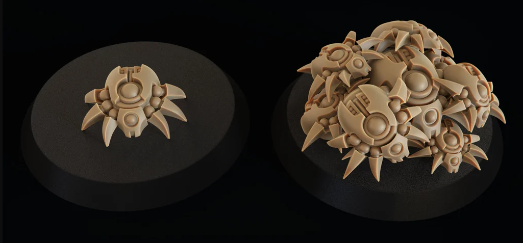
First step is to open the file in Blender to see what we’re working with. We’ll open the single scarab model and the base. Since we’ll be printing with a FDM or FFF printer we’re interested in the single scarab model because we won’t have the resolution to print the scarab swarm. The swarm model is better suited to resin printers which have a higher resolution.
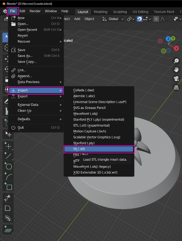
Importing the STL files into Blender was completed by File>Import>STL.
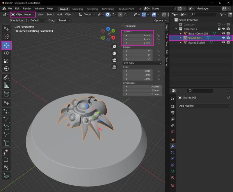
Models can be moved around using the Move tool or entering values in the transform section in object mode. With a model selected the Move tool can be used by dragging the blue, green or red arrows.
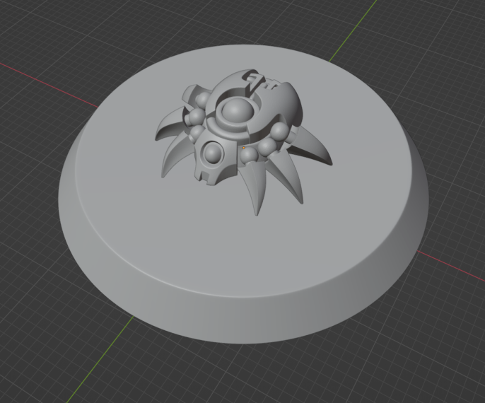
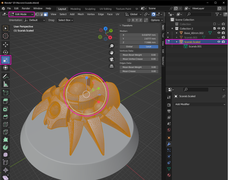
The first edit was scaling up in size to make the details easier to print on my FDM machines. I scaled the model up in edit mode with the Scale tool while using the base as a reference. To universally scale select the white circle and drag.
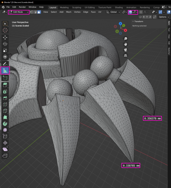
The next edit was using the Boolean modifier to remove the tips of the legs. This was guided by measuring the features, slicing the files and test printing. Measuring the features in Blender showed that were just below 0.4mm which is the smallest size the printer can resolve due to the 0.4mm nozzle size.
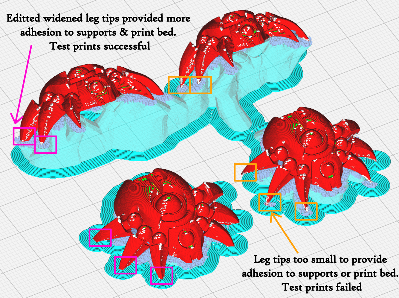
From the sliced test print we can see that the small tips of the legs won’t provide enough area to adhere to the supports.
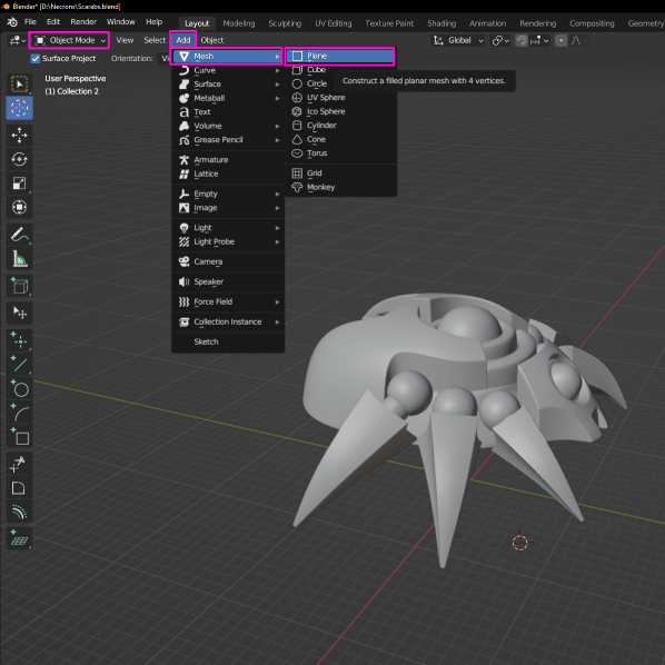
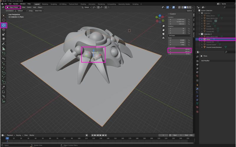
To begin using the Boolean modifier to remove the leg tips a plane needs to be added which will act as our cutting/trimming tool.
With the plane selected in object mode we can resize it by entering values for x and y under dimensions. Moving the plane can be done dragging the arrows with the move tool selected.
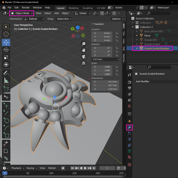
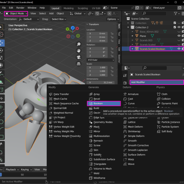
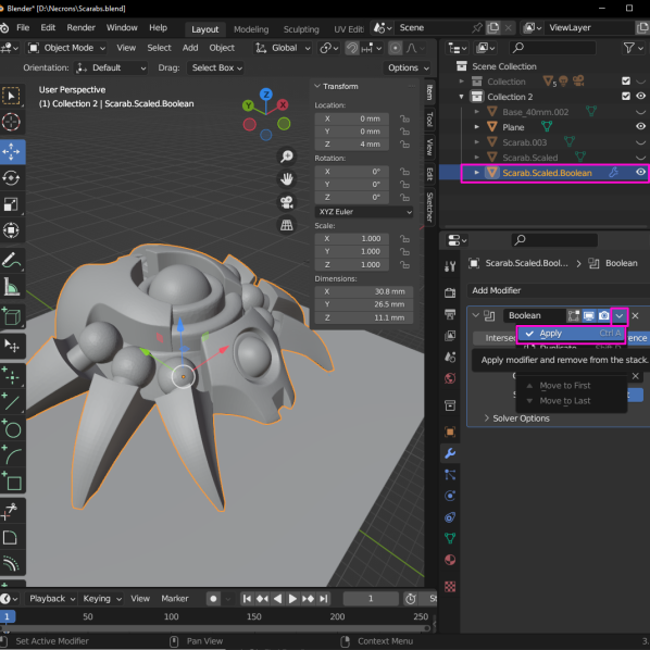
To select the Boolean Modifier we need to be in object mode, and then with the Scarab model selected we can click the Modifier (spanner) icon. The Boolean Tool was selected from the Add Modifier drop down.
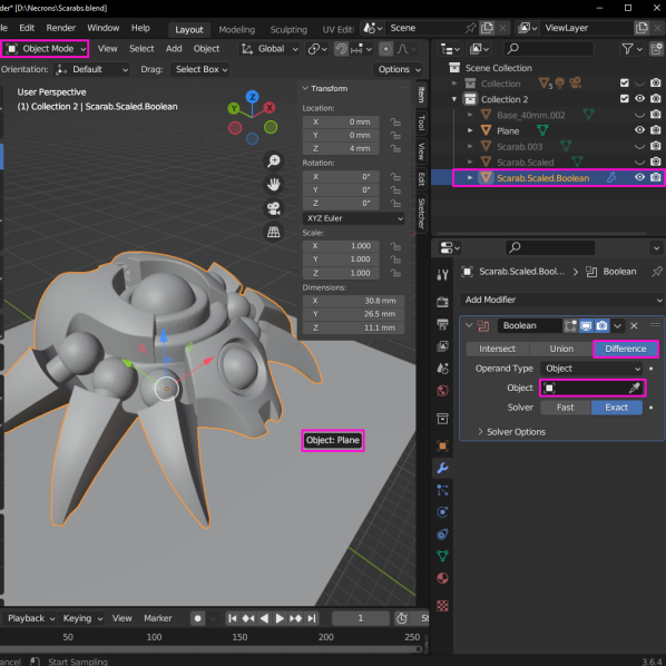
With the Boolean Modifier added we now need to select the Plane as our second object. This was done by clicking the dropper bottle then the Plane from the view port.
The final step is to apply the Boolean Modifier by selecting the drop down arrow then Apply from within the Boolean Modifier.
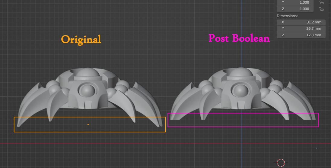
With Boolean applied the tips of the legs should be removed. The image below shows the post Boolean result for the model orientated horizontally.
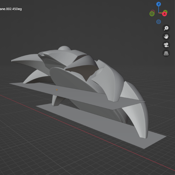
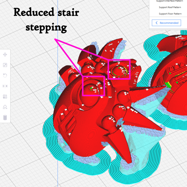
For 3D Printing a model was orientated at 45 degrees. To edit this model two planes needed to be created along with a Boolean Modifier for each. The image below shows the location of the two planes.
3D Printing
The first two models were orientated horizontally and at 45 degrees. This was done to assess which orientation produced the best details while reducing prep time before painting.
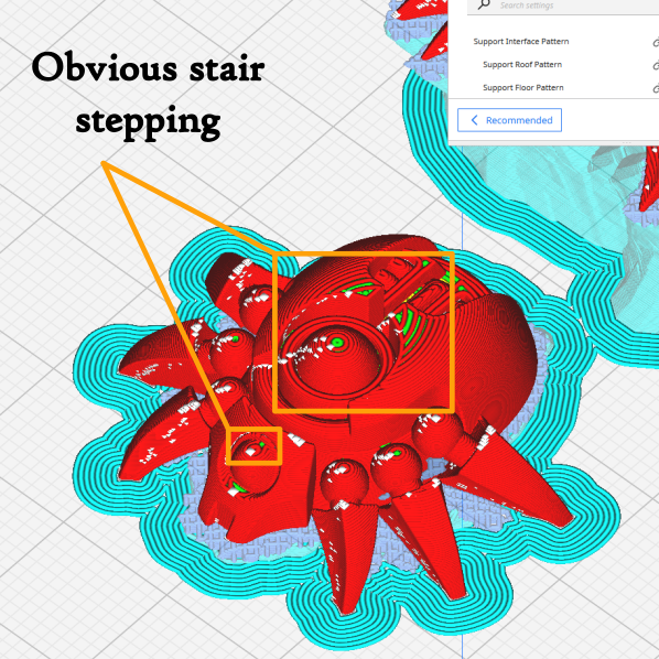
Reorientating models is a great technique for increasing detail resolution because it allows the layer lines to be positioned relative to model details. As shown below, there is obvious stair stepping on the horizontal model due to shallow slopes on the model. The model sliced at 45 degrees has less stair stepping and where does it occur can be access with sand paper to prep before painting.
Printing parameters used to slice the models are summarised below. When selecting wall and layer counts I considered that the models be will sanded prior to painting, so I increased these values.
| Parameter | Value | Unit |
| Layer Height | 0.12 | mm |
| Infill | 35 | % |
| Top Layer Count | 8 | – |
| Bottom Layer Count | 8 | – |
| Wall Count | 3 | – |
| Nozzle Size | 0.4 | mm |
| Printing Speed | 40 | mm/s |
| Bed Temperature | 60 | DegC |
| Extruder Temperature | 200 | DegC |
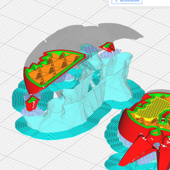
Given the design of the model the support parameters were tweaked. Tree type supports were used as this allowed the supports to branch out to legs. To make the bulk of the support easier to remove a concentric support pattern was used. This pattern, shown below, can be collapsed into itself with small pliers which is what makes removal easier.
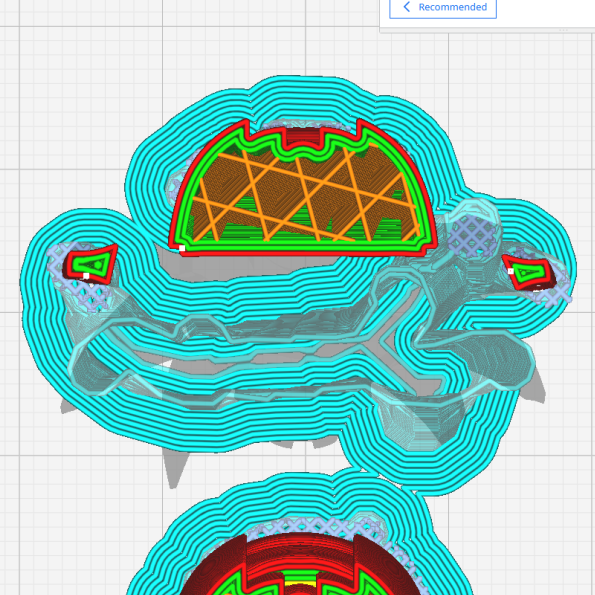
To ensure there was support material under the model, the Support Interface Thickness and Density were increased. Increasing these parameter additionally makes the interface layer rigid enough to be removed to large sections, if it does not remove in one piece.
| Parameter | Value | Unit |
| Support | Tree | – |
| Support Pattern | Concentric | – |
| Support Z Distance | 0.12 | mm |
| Support Interface Thickness | 0.96 | mm |
| Support Interface Density | 100 | % |
| Support Interface Pattern | Grid | – |
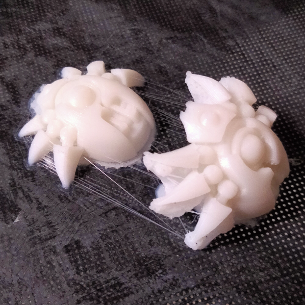
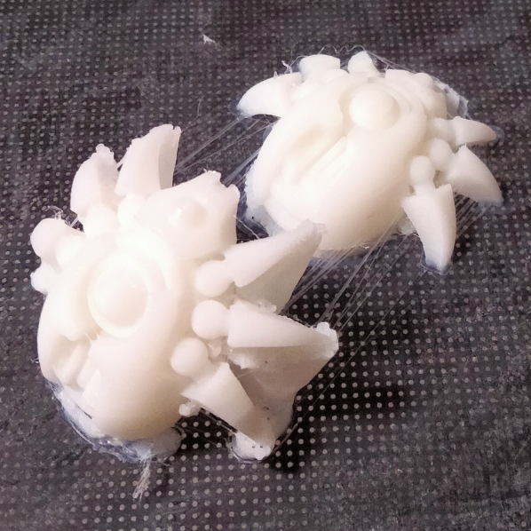
Below are the first two printed models. White filament is great at hiding print imperfections. In this case we’ll need to prime these models before we begin preparing them for painting, as the primer will highlight the imperfections.
Preparation
There was some sanding, a lot of sanding!
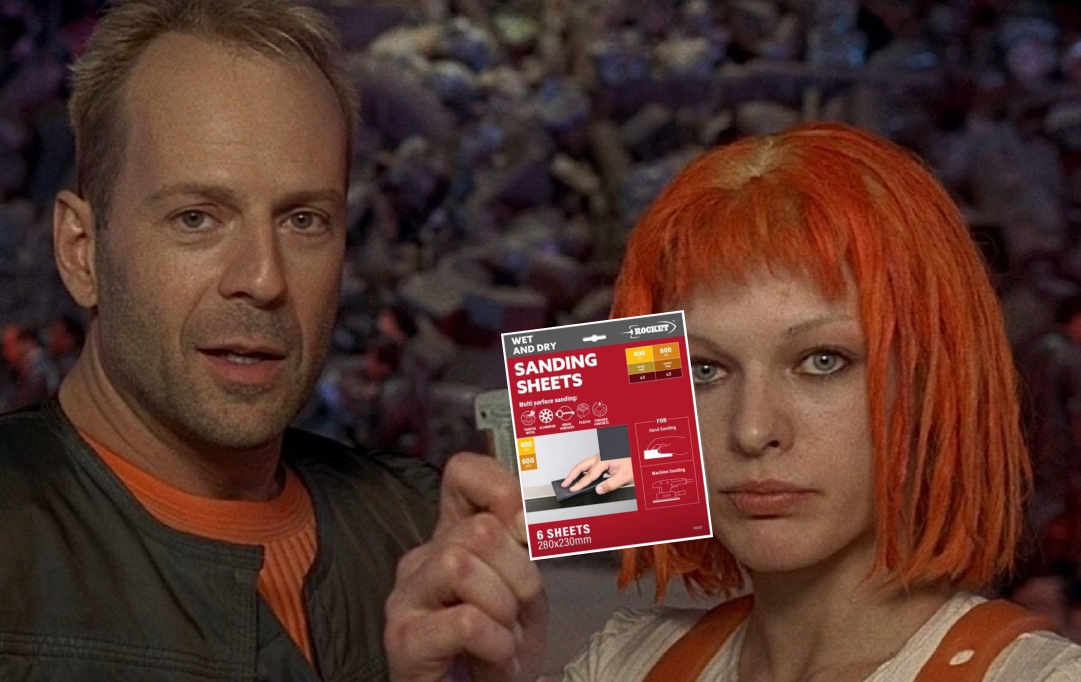
I made use of 400 and 600 grit sandpaper for the bulk of the prep work, before moving onto 800 and 1200 grit after the models received a couple coats of primer.
Wet sanding helped contain the dust while using my paint booth extractor and wearing a mask. Not many tricks to the sanding stage except grabbing wet and dry sandpaper multi packs and primer from the hardware store.
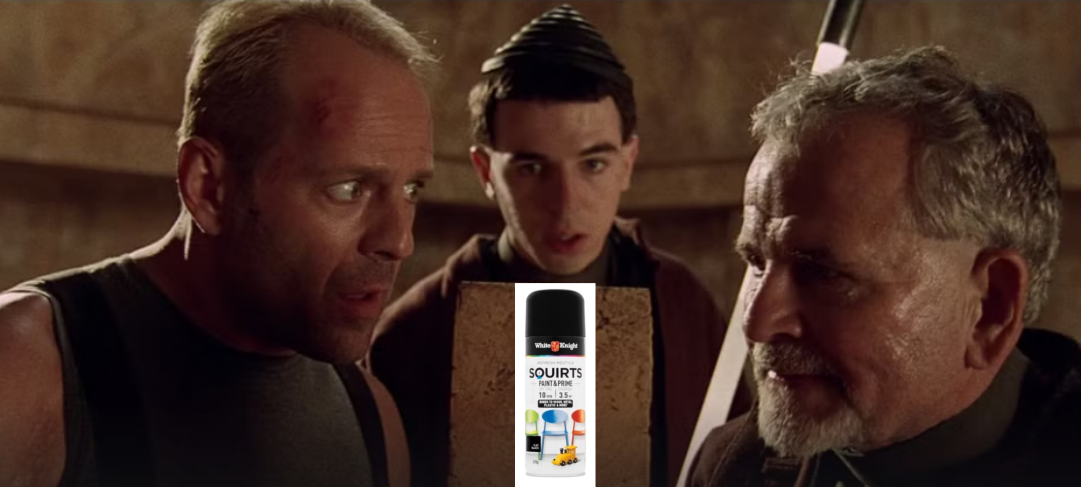
The hardware store primer I favour for preparing 3D printed models is White Knight SQUIRTS. I’ve found this primer goes on a bit thicker than other brands, while not completely obscuring details. This extra thickness helps blends in layers lines, but extra care is needed not to spray on too much. Warming the can up in water and shaking well will give more control over the spray.
After a few rounds of sanding, priming and sanding the models arrived at the “trust the process” stage.
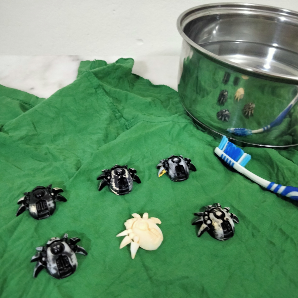
The next stage was giving these models a scrub in soapy water and a final coat of primer. With all the sanding and handling these model have been through this scrub will help get a smooth finish with the final layer of primer.
Painting
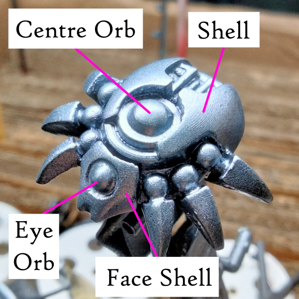
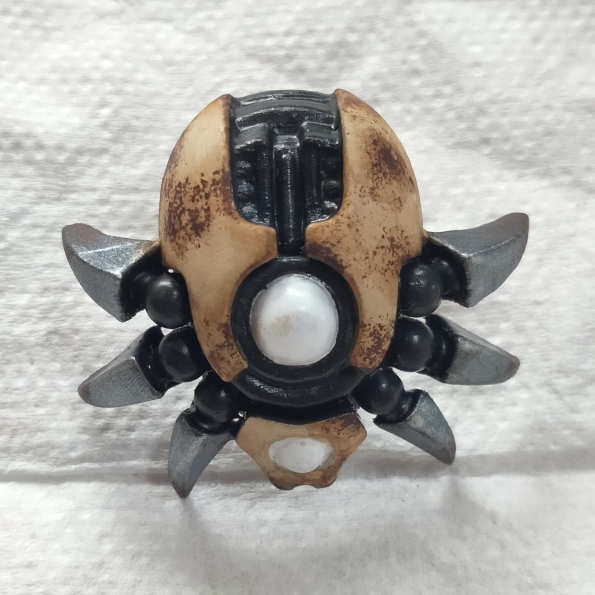
I decided on a painting approach for these models by choosing features that I wanted to stand out. They were the orbs, and shells on the rear and head.
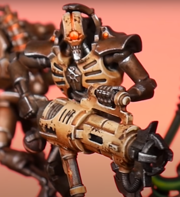
To highlight the shell features I attempted to emulate a paint scheme Trovarion Miniatures demonstrated on his painting 10th edition Necrons video.
For the orbs I’m targeting a glowing effect by using my airbrush and hand brushing on highlights.
Base Painting
Painting began by air brushing the models gunmetal as I initially wanted all the mechanical details to be metallic. I dialled this back as I found it highlighted the mechanical details too much.
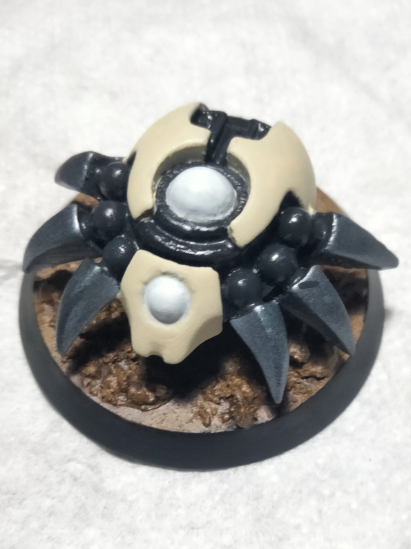
I decided on a dark grey for all the mechanical details, minus the leg tips. The base coat for the shells was Bone White, while the orbs were based with an Artic White. By giving the orbs a base coat of white the next layer of airbrushed Teclis Blue should appear brighter.
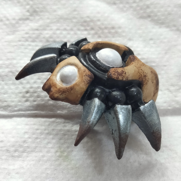
Sponging & Washing
I salvaged a tiny piece of sponge from my old headphone cushions and focused on the shell and tips of the legs.
When sponging the shells, I aimed to add enough detail to break up the smooth surfaces. And by sponging the lower edges I wanted to hint at environmental wear.
With the sponging completed I started with the wash.
I used Seraphim Sepia Shade from Citadel and began with two light coats over the shells. Then I went back in and added more shade on the sponged areas and around the lower edges of the shells. By applying the wash in this way I wanted to tie together the sponged brown and bone white to further sell the environmental wear effect.
Air Brushing
This stage took as long as the entire base painting stage as I focused on building up the glow effect slowly. I had the pressure set around 20 psi and thinned the Teclis Blue paint with water. For thinning I added a little more water than paint to to help with building up thin coats.
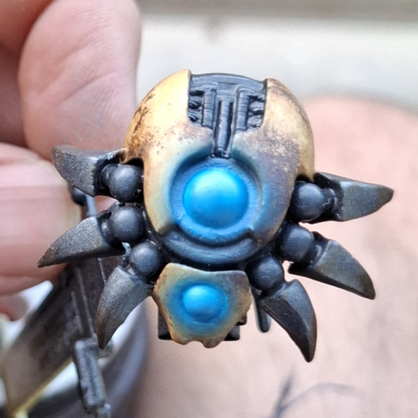
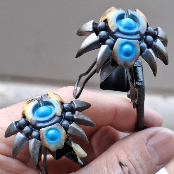
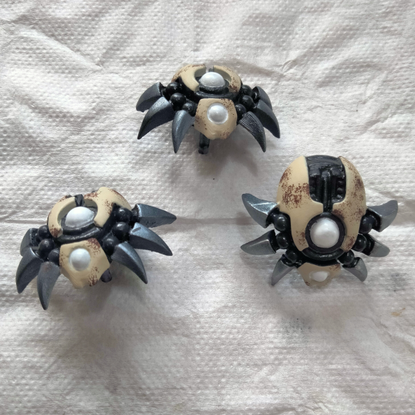
I brought the models outside multiple times during this stage to check the air brush coverage. The lighting in my spray booth is too direct and the brighter ambient light outside helped confirm the glow effect was on target. These photos taken with models outside were a great guide for highlighting the glow effects.
Highlights
Being guided by the above photos I highlighted the glow effects with Artic White. I used my pointiest brush and thinned the paint with liquefying medium and water.
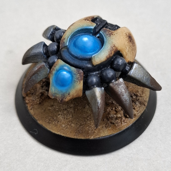
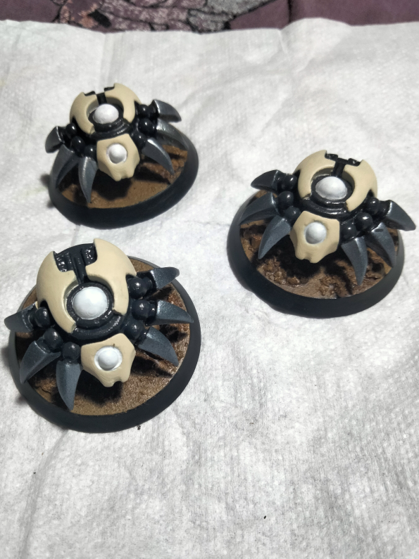
Final Photos & Thoughts
I thought the sanding stage would never end, but by test printing the models in different orientations I saved myself time. By not top coating the models before air brushing I had to act quickly with a damp brush to clean up mistakes. This stage would’ve been less stressful if I took the time to top coat.
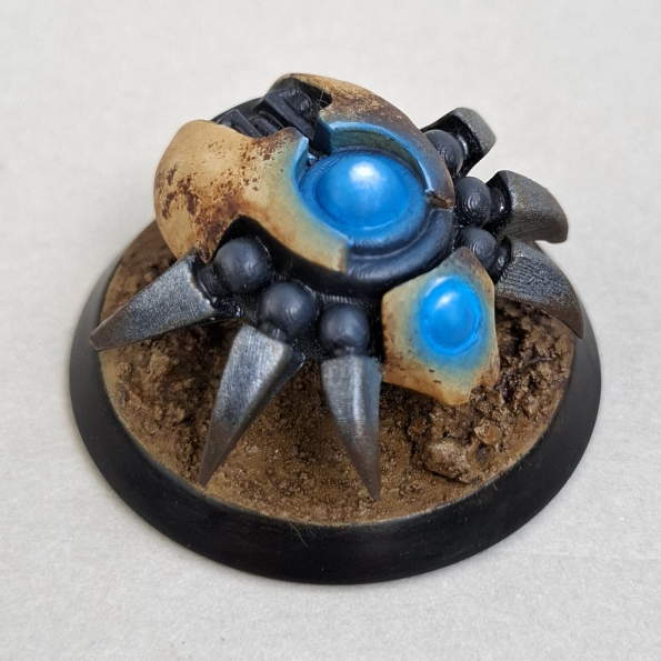
I’d like to say taking the photos of the models outside after air brushing was all planned to help highlighting. I’m really glad with how the highlighting finished up, I will definitely try again on second unit of Scarabs I printed!
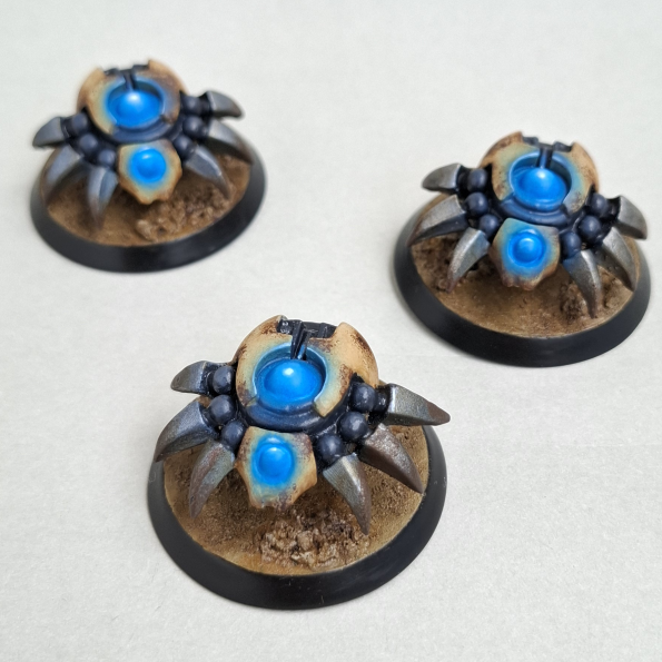
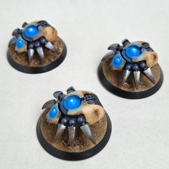
Head to the gallery for more work in progress and finished photos!